Olmstead Locks and Dam Project
Barge Mounted Maxcretes Deliver Concrete for Olmstead Locks and Dam
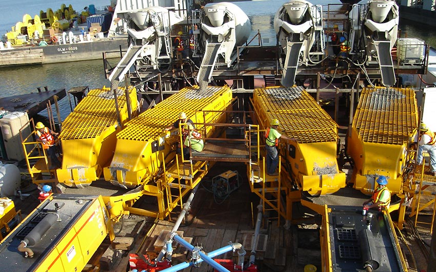
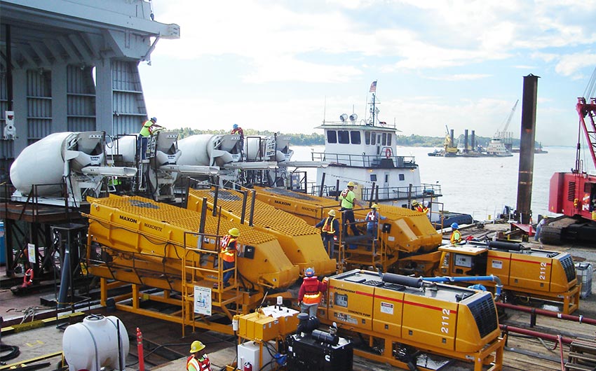
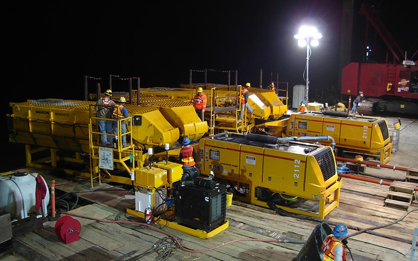
Redi-mix trucks deliver concrete to Maxcretes that feed to trailer pumps.
CONTRACTOR
LOCATION
Ohio River, USA
APPLICATION
EQUIPMENT
SHARE:
OVERVIEW
The Original Article: BUL-469-In-The-Wet-Job-Report-Washington-Group
As part of one of the last phases of the Olmsted Locks and Dam Project, a Putzmeister concrete placing system is placing up to 140,000 cubic yards of tremie concrete via the “in-the-wet” method, a first in the U.S., for the new replacement locks and dams numbers 52 and 53.
Located on the Ohio River which begins in Pittsburgh, Pennsylvania and flows west 981 miles to the Mississippi River at Cairo, Illinois, are 20 locks and dams that provide a nine-foot deep year round channel for navigation, which allows the traffic on the river to descend a total of 460 feet, from 710 feet at Pittsburgh to 250 feet above sea level at Cairo, Illinois. The continued increase of waterborne commerce on the Ohio River has required periodic improvements in the waterways transportation infrastructure.
Two of the current locks and dams, numbers 52 and 53, originally built in 1929 and located on the Ohio River between Paducah, Kentucky and Cairo, Illinois, cannot meet the current and future traffic demands without significant delays because of their age and dated design.
As a result, the U.S. Army Corps of Engineers (the Corps) and the navigation industry are replacing locks and dams numbers 52 and 53, with one of the largest civil works projects undertaken by the Corps.
Construction of the 20th and final lock on the Ohio River, known as the Olmsted Locks and Dam Project, at river mile 964.4, was authorized by the U.S. Congress on November 17, 1988, by passage of the Water Resources Development Act of 1988 (Public Law 100-676).
Construction for the project began in November 1992.
Several phases make up the Olmsted Locks and Dam project:
- Access road/ Resident engineer’s office (Completed June 1994)
- Lock cofferdam (Completed December 1995)
- Lock construction (Completed March 2002)
- Bulkheads (Completed July 2005)
- Lock approach walls (Completed April 2004)
- Dam construction (Completed September 2018)
- Demolition of locks and dams 52 and 53 (upon completion of the dam construction)
The joint venture Washington Group/Alberici (WGA) was awarded the $564 million contract from the Corps for construction of one of the last phases of the project, which includes constructing a 2,700-foot-long concrete dam across the river. The dam will comprise five 110-foot tainter gates and a navigable pass section with boat-operated wicket gates along with a fixed weir tying the dam into the Kentucky bank.
Construction began in spring 2004 and the estimated completion date is December 2015.
THE METHOD
The dam is being constructed using the in-the-wet method, a first for the Corps on a dam of this size. The in-the-wet method is the construction of a dam under water. Normally, the water is drained out of a cofferdam and the construction work is done in-the-dry. The in-the-wet method was employed because the Corps was convinced this method would be cheaper, faster and have less impact on the environment than using conventional cofferdams.
“There is nothing standard about this job,” says “The in-the-wet method required us to think outside of the box to figure out how we would construct the dam underwater. We had to determine which equipment would be the most efficient in this unique job environment.”
-James Whitworth, WGA Marine Engineer
THE APPROACH
As part of the dam construction, precast shells are being constructed on land adjacent to the dam location and are being carried into position and set underwater on a prepared bed of select fill, piles and continuity rebar grids.
Once the shells are in place, concrete is tremied under the precast shells to form a continuous bond between the piles, rebar, and surface shell, and provide more strength and fuller foundation overall for the dam.
WGA consulted with Putzmeister’s Special Applications Business (SAB) to help decide what equipment would be best suited to deliver the tremie concrete. Because of the importance of everything working correctly for the entire length of every 36-hour pour, the mix design was reviewed and trial-run testing was carried out under cold-weather conditions to determine the level of pumpability of this “sticky” mix.
Whitworth explains, “After discussing with SAB the specific needs of the project and the environmental circumstances, we determined that they could provide us a complete concrete delivery system for dam construction. Because they manufacture and provide every component of the system, that’s huge because it means less time I have to search for another company that has the other system components needed.”
The equipment that SAB proposed was selected and arrived on site in early spring 2010. Included were:
- (2) freestanding MX 43/47Z-meter placing booms mounted on two freestanding pin towers
- (1) 31-meter placing boom
- (2) BSA 2112 skid-mounted concrete trailer pumps
- (1) 40-meter truck-mounted concrete boom pump
- (4) Maxon Maxcrete IV 18 cubic yard remix hoppers
- (2) DVH 5/2 diversion valves
MOVING THE MIX
The tremie concrete mix being used is self-leveling to ensure that it fills up every square inch under the shell for ultimate strength. “The mix’s strength is 5,000 psi at 90 days and has a 10-inch slump,” comments Whitworth. “It does not need any vibrating.”
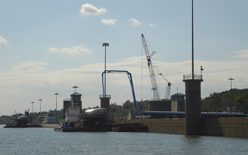
Placing the concrete for each of the 28 shells is a non-stop 36 hour, step-by-step process. First, the 40-Meter truck-mounted concrete pump, located on the river side of the project, delivers the concrete through 300 feet of slickline across the lock chambers.
At the end of the slickline is the 31-meter placing boom that delivers the concrete into four stationary mixer drums on each of the two delivery barges. “The 31-meter placing boom is perfect for customized applications like ours, providing us the utmost versatility in the concrete placement process,” notes Whitworth.
Next, the delivery barges go to the placing barge where stationary mixer drums dump the concrete into the remix hoppers. These two delivery barges constantly rotate between the 31-meter boom and the placing barge to provide the most efficient placement of concrete during the non-stop pours.
The remix hoppers then place the concrete into the hoppers of the trailer pumps. “The remix hoppers offer fast loading, fast discharge and complete remix capabilities,” says Whitworth. “And those characteristics are crucial to the project given our non-stop pour process; it’s almost as if this style of remixer was made specifically for this project.”
“The two BSA 2112 trailer pumps’ performance has been outstanding,” comments Whitworth. “We’ve been averaging 100 cubic yards per hour from each pump but they are capable of pumping up to 142 cubic yards per hour. The rate of output from these trailer pumps has been vital in ensuring we stay on track, considering how much concrete needs to be placed.”
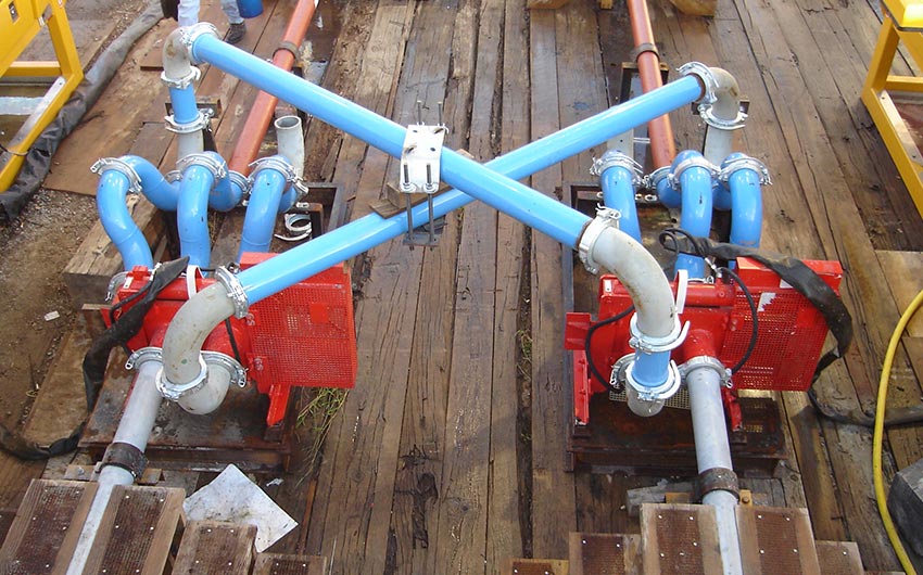
Two DVH 5/2 diversion valves are hooked up between the trailer pumps and the placing booms.
“The diversion valves have been an added support of muscle within this system,” explains Whitworth. “They provide the flexibility to use either trailer pump with either placing boom, and provide cleanout routes. In addition, the valves can easily handle high pressures up to 1,885 psi without leaking.”
After the trailer pumps and diversion valves, the concrete travels up to the two MX 43/47Z placing booms. Here is where the concrete is delivered to the tremie pipes that move it underwater to its final resting place underneath the precast concrete shells.
The two Z-Fold, five-section MX 43/47Z placing booms are the largest placing booms in the industry that do not require a counterweight.
“Not needing a counterweight on these placing booms saves us time and reduces labor costs,” says Whitworth. “Anywhere we can save time and money is a huge benefit to us. Plus, their monstrous 138-foot one-inch horizontal reach places concrete exactly where we need to into the tremie pipes,” he adds. “With these pours being nonstop, we don’t have time for a system that doesn’t place the concrete precisely where it needs to be.”
To date, the concrete placing system has delivered 2,000 cubic yards of concrete for one precast shell. The system will deliver up to 5,000 cubic yards of concrete for each of the remaining pours, and is estimated to be on site through 2015.
THE TEAM & EQUIPMENT
Project Team
Owner/Developer: U.S. Army Corps of Engineers
General Contractor & Concrete Ready Mix Supplier: Washington Group and Alberici Constructors, INC a Joint Venture (WGA)
Concrete Equipment