NYC Water Tunnel No. 3
Agitors and Maxcretes Handle Harsh Concrete Mix in NYC Water Tunnel
New York City Water Tunnel No. 3

OVERVIEW
The New York City Water Tunnel No. 3 is the largest capital construction project in New York City’s history. Constructed under the direction of the New York City Department of Environmental Protection (DEP), the completed tunnel will stretch over 60 miles and take 50 years to construct in its entirety. When completed, City Water Tunnel No. 3 will join Water Tunnels No. 1 and No. 2 in supplying water from reservoirs in Upstate New York to the residents in all five boroughs of New York City.
City Water Tunnel No. 3 is being constructed for 2 primary reasons.
- Water Tunnel No. 1 and 2, placed in service in 1917 and 1936, respectively, have not been inspected and repaired since they were opened. By constructing and opening No. 3, the city will be able temporary close the original two tunnels for inspection and repairs while No. 3 continues to supply water to the city.
- With the continued growth of New York City’s five boroughs, a third tunnel will be needed to supply water to the larger population.
THE STAGES
City Water Tunnel No. 3 is divided into 4 stages:
Stage 1 has been completed and was put into service back in 1998 supplying water 13 miles from Yonkers through Manhattan and across Central Park .
Stage 2 is under construction and consists of two sections, one under Manhattan, and one under Queens / Brooklyn. The tunnel consists of 5 miles of 23’ diameter rough bore with a 20’ diameter finished full concrete liner, (18” thick).
Stage 3 will be a 16 miles long section of tunnel from Van Cortlandt Park Valve Chamber in the Bronx to the Kensico Reservoir in Westchester County. Water will be able to get delivered from the Valve chamber to tunnel No. 3 or to the Hillview Reservoir to tunnels No. 1 or 2.
Stage 4 will be a 14-miles long section from the Van Cortlandt Park Valve Chamber through the Bronx traveling under the East River into the Flushing area of Queens.
THE CHALLENGE
Thus far, there have been three obstacles that have made the construction of this tunnel particularly difficult.
- With a section of the tunnel being constructed directly below the Queens Borough, the J.V. is required to keep noise and traffic to a minimum. A relatively small job site was selected for the drop shaft, with limited space for equipment staging, offices, mining spoils removal, and concrete delivery trucks. The J.V. was required to remove the tunnel spoils (brought up from the tunnel mining below) via rail cars, instead of dump trucks.
- The tunnel owners, NY City Department of Environmental Protection, required the J.V. to use an “older” concrete mix design, utilizing 1 ½” trap rock (granite) and little cement. Transporting, placing, and pumping this “mix” was difficult. Grow Tunneling, the project sponsor and a local contractor, had previous experience with this mix design. They knew that the concrete system they would choose, would be critical to ensuring that the concrete was still usable when it reached the forms.
- The tunnel was constructed in bedrock that consisted of extremely hard trap rock. The Tunnel Boring Machine (TBM) purchased by the J.V. encountered numerous delays. “Having excavated a number of tunnels before in New York, we knew going in that the tunneling would be slow, “ commented Len Epstein, VP, Grow Tunneling. “However, once we got into the tunneling phase, we had numerous delays and spent countless hours/days changing out cutters.” By the time the TBM had completed the rough bore, the J.V. was already months behind schedule.
The J.V. turned to Maxon Industries looking for ways to transport and place the concrete underground faster than previous methods utilized in New York.
THE SOLUTION
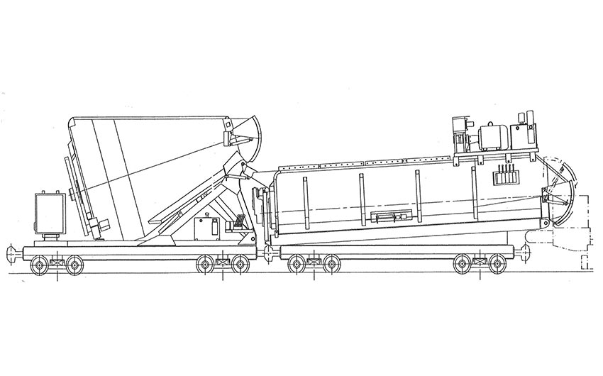
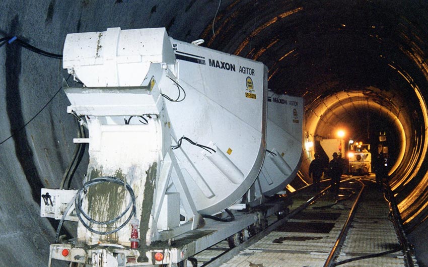
Maxon Industries proposed a system consisting of Maxon Agitors and Maxcretes. Trains of rail mounted Maxon Agitors transport the concrete from the drop shaft to the forms. A Maxon Maxcrete Remix Surge Hopper then accepts the concrete from the Agitors, remixes the concrete, and feeds a continuous stream of concrete to the pump. Before the J.V. placed the order for the concrete system, Maxon Industries and the J.V performed a study comparing the Maxon system to previously used methods. The system of Maxon equipment was found to be capable of delivering concrete up to 50% faster (theoretical) than previous methods utilizing agitating cars (revolving “drum style” mixers on railcars). In the fall of 1998, Grow purchased and placed into service 12 Maxon Agitors and 2 Maxcretes.
THE EQUIPMENT
Ferrara Bros., Flushing, NY, supplied the concrete to the jobsite/drop shaft. The harsh concrete mix consisted of 1 ½” trap rock with a low cement content, and super plasticizer added at the plant. The concrete had a slump of roughly 7” at the plant, 6” at the drop shaft, and 4” when it reached the head. Transit times from the plant to the site averaged 25-35 minutes.
All the concrete for the entire length of the 25,504 linear foot tunnel was delivered to a single drop shaft at the end of the tunnel. At the bottom of the drop shaft, approx. 750’ underground, trains of 3 Agitors on rail cars would be filled with 13 cubic yards of concrete each. The open top of the Agitors made for rapid loading and easy inspection.
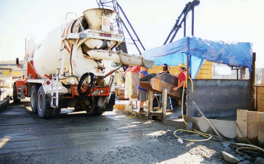
Ferrara Bros supplying concrete down drop shaft.
Each Agitor was specially equipped to handle the harsh mix. Heavy-duty agitator shafts with T-1 steel paddles were installed to prevent any bending of the paddles/arm. The force of dropping the concrete 750’ down the drop pipe caused some segregation, but was corrected by the agitator shaft of the Agitors and the agitation in the Maxcrete located at the pump.
The Agitors were also equipped with high torque, heavy-duty hydraulic motors powered by electric motors to keep the agitator turning in the low slump – harsh aggregate concrete. When the Agitors reached the head of the tunnel, they were plugged into the power supply of the tunnel to power the electric motor, and the hydraulic functions.
After all three Agitors were fully loaded (approximately 8 minutes for 39 cubic yards), a locomotive would transport the three Agitor rail cars to the head of the tunnel. Actual transit times varied, with a maximum transit time of 55 minutes when the forms were furthest from the drop shaft. The J. V. installed a California switch at the drop shaft and midpoint in the tunnel to allow the train of loaded Agitors to pass the empty cars returning to the drop shaft.
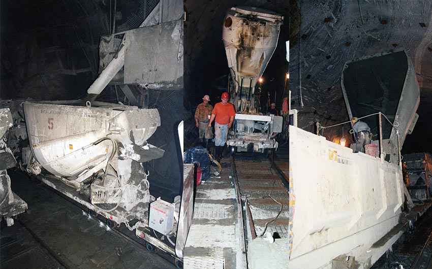
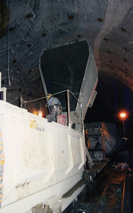
When the train of loaded Agitors arrived at the head, the locomotive would push the train of three Agitors up on to an elevated rolling platform/bridge. The bridge, provided by Everest, included a switch, which allowed two trains of Agitors to pass while on the bridge. As the tunnel formworks progressed, the bridge (with the pump, Maxcrete, and Agitors) would be moved. Once on the bridge, the train of full Agitors would be backed up to the rail mounted Maxcrete, then be plugged into the power supply to begin agitating the concrete. After a few revolutions, the Agitor would begin discharging the complete load into the Maxcrete. Both units were equipped with short transfer chutes to allow for fast concrete flow from one to the other. The large gate of the Agitor allowed for full discharge of 13 yards of low slump concrete in less than 2 minutes.
While the first Agitor was discharging, the coupler between the 1st and 2nd cars was released and the locomotive would pull the 2nd and 3rd Agitors back approximately 20’, just behind the switch. The switch would then be thrown. When the 1st Agitor was done discharging into the Maxcrete, the locomotive would back further, pulling the now empty 1st Agitor car back through the switch, and onto the parallel track, out of the way. The cable would be disconnected and the locomotive would then push the two full Agitors toward the Maxcrete. The 2nd and 3rd Agitor in turn would then be positioned by the locomotive, discharge their full loads, and be pulled back through the switch. The complete cycle of discharging all three Agitors took less than 10 minutes.
“The total discharge time for all three Agitors was definitely faster than with our old concrete system (revolving style mixer drum). The savings in time kept our concrete production moving at maximum speed.”
-Don Hickey, Project Engineer
While the Agitors were discharging into the Maxcrete, the Maxcrete would be remixing the concrete, ensuring the best possible concrete delivery to the pump. The Maxcrete’s bi-rotational 18 paddle horizontal mixing shaft allowed even the stiffest loads to be remixed. By the time the concrete reached the Maxcrete the slump was approximately 4”, with some loads under 1” slump.
The Maxcrete was specially built to connect directly to the hopper of the Schwing pump supplied by Ken Williams of Pumpcrete. Pumpcrete, in turn, modified their pump hopper to exactly match the shape of the Maxcrete discharge gate. The result: a seamless transition from the Agitors to the Maxcrete remix surge hopper to the pump hopper, without any conveyors. “The fit between the Maxcrete and the pump was excellent,” commented Jim Disley, Equipment Superintendent. “We were concerned about having to use conveyors in any concrete system. Maxon and Pumpcrete offered us a great solution without the conveyors. It was maintenance free option.”

The pump supplied concrete to the 480 linear feet of Everest forms through an overhead slick line. Because the contract required the J.V. to bulkhead each time they stopped placing, the concrete system would run 24 hours a day, Monday through Friday. The 18” thick concrete lining took 3.78 cubic yards per linear foot. As the J.V. got closer to the drop shaft, and transit times were reduced, production reached over 5,000 cubic yards per week.
Alan Paskoff, Project Manager stated, “We had difficulties at first utilizing the concrete system at its full capacity, but Maxon was very supportive and we worked through it. Once we had all the pieces and personnel working together, we made very good time. We would never return to the old method of using revolving drum style agitator cars.”
“We had a lot of obstacles to overcome in the project: only one drop shaft, a harsh concrete mix, the New York labor pool…” mentions Don Hickey, Project Engineer. “But when the project was completed, we knew that our decision to use Maxon equipment was a definite time saver.”
Download or Print the PDF Version: